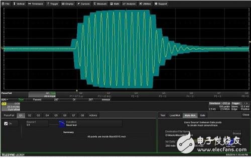
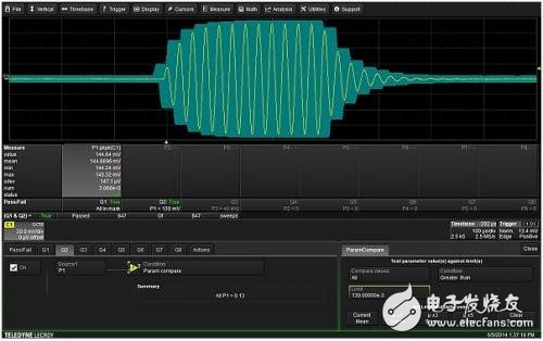
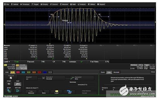
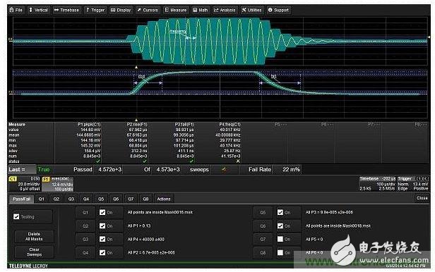
Have you used the pass/fail tesTIng function in a digital oscilloscope? This is a great tool if you need to perform repetitive testing on small batches of equipment. You can also use the pass/fail test in an automated test environment. Doing this test with an oscilloscope is usually much faster than transferring the entire waveform to a computer and then processing it offline. Many today's benchtop oscilloscopes offer multiple levels of test standards. These test standards are divided into two broad categories: template or template testing and parametric limit testing. The template test compares the captured waveform to a user-defined template. The parametric limit test is based on the value of the waveform measurement, such as amplitude or frequency. In each category, you can choose the appropriate logical operation to define whether the waveform passes. Pass/fail testing of an actual waveform is the best way to explain it. In this example, an ultrasonic sensor will be used as the device to be tested. The device produces a 40 kHz burst of approximately 600 μs and the burst exhibits an exponential rise and fall. Here is a very simple test example, creating a simple tolerance template around the waveform and then testing whether the waveform is inside the template. The pass/fail test of the oscilloscope used in this article supports up to 8 test conditions. Each test condition is called Qn and can be set individually as a template test or a parameter limit test. Figure 1 shows the tolerance template and waveform created with test condition Q1. Tolerance templates are created by setting the horizontal and vertical test limits entered by the user. Oscilloscope vendors also provide related template creation tools, but not directly on the basis of waveforms. Templates can be imported into the oscilloscope via the Load Mask feature. If all points of the waveform are within the template, the Q1 test condition is true. Other choices for test conditions are if all points are true outside the template, if any points are true within the template, or if any points are true outside the template. Figure 1: A tolerance template can be built around the output waveform of the device under test. The template limit is 0.2 squares from each point on the waveform in the vertical and horizontal directions. This test tells us that the waveform is completely inside the template. But what if the waveform amplitude is too small but still inside the template. We can increase the peak-to-peak amplitude test of a waveform to ensure it has the smallest amplitude. As shown in Figure 2, the test standard for testing Q2 is to compare the parameters with the peak-to-peak amplitude to see if it exceeds 130mV. Figure 2: The second test condition verifies that the peak-to-peak voltage of the waveform must exceed 130mV. This test condition, along with the template test in Q1 above, requires that all test conditions be true (and logic) to produce a "pass" result. Other options include "anything true", "all false", "any false", "all Q1-Q4 or all Q5-Q8", and "arbitrary Q1-Q4 and any Q5-Q8". Measuring the rise and fall times of the modulation envelope is another required test. It is difficult to do this test directly on the captured waveform. However, if you extract the modulation envelope, you can easily measure the rise and fall times. Demodulation is achieved by using absolute values ​​(full-wave rectification) and then low-pass filtering the results. The low pass filter can be implemented with an enhanced resolution function of the oscilloscope. Figure 3 shows this operation and the measurement of the rise and fall times of the modulation envelope. The extracted envelope is superimposed on the original waveform to show how perfect it is to track the 40 kHz carrier peak. The rise and fall times are measured on the mathematical trace F1. The frequency of the carrier is measured on the original waveform C1. Figure 3: The mathematical function F1 extracts the modulation envelope and then measures the rise and fall times of the envelope. Test condition Q3 is based on a C1 frequency of 40 kHz ± 400 Hz. The rise time is used as the basis for testing Q4 and must be within ±2μs of the average value of 67 μs. Similarly, the rise time of the Q5 test is required to be within ±2μs of the nominal value of 99 μs. Testing the waveform amplitude with peak-to-peak values ​​only tests a single sample pair (maximum-minimum sample) on the waveform. It does not see the entire captured waveform. You can do this by creating a template around the modulation envelope (tracking all carrier peaks) and then testing if the envelope is inside the template. Figure 4 shows the final test using six "and" test conditions. Figure 4: Complete test setup using six test conditions, including two templates, peak-to-peak amplitude, carrier frequency, and rise and fall times of the modulation envelope. The final step is to choose the action to take based on the test results. There are 6 possible actions to choose from: Jiangmen Hongli Energy Co.ltd , https://www.honglienergy.com


â— Stop acquisition â— Save waveform â— Send audible alarm â— Save hard copy of test â— Generate LabNote report â— Output an electronic pulse from the oscilloscope's auxiliary output connector Any or all of these actions can be performed as test results. In addition, the status register reports the test results and the oscilloscope can also issue a service request to the external controller. Most test engineers will ask for test time, which is related to the model of the oscilloscope. For this oscilloscope, the basic signal acquisition and calculation of the modulation envelope takes approximately 43 ms. If you carry out all measurements (parameters P1 to P4), this time will increase to 51ms. Testing against all six standards will extend the total test time to 68ms. Measurement and testing only adds 25 ms to the basic acquisition. If you want to transfer data to an external controller using IEEE-488 (assuming 250kbps), it takes 10ms to transfer 2500 points of waveform. From this perspective, all measurements and tests must still be completed. The pass/fail test only requires you to transfer the test results without having to write all the test code. The pass/fail test is an excellent way to use an oscilloscope in a test. It is fast, flexible, and efficient, and can be used to perform signal acquisition, data processing, measurement, and test functions with a single instrument.
March 16, 2023