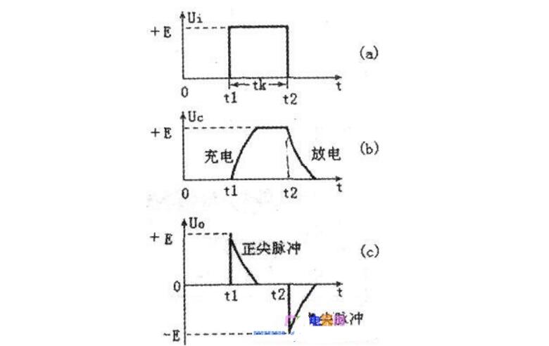
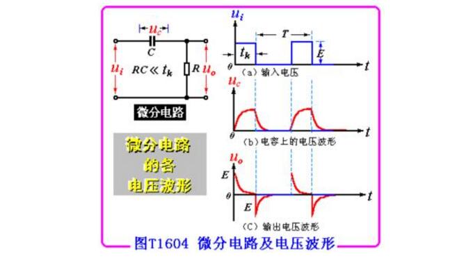
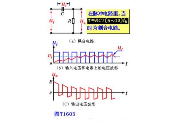
The RC differential circuit is a widely used circuit for transforming a pulse signal. It usually converts a rectangular pulse signal into positive and negative bidirectional spikes. Mathematically, this sharp pulse is approximately equal to the differential form of a rectangular wave, so it is called a differential circuit. The characteristic of the differential circuit is that the output can quickly reflect the transition component of the input signal. That is, it can select a sudden change in the input signal. The output has a narrow pulse width and contains "differential" meaning compared to a waveform with a wide input pulse width. The output pulse of the RC differential circuit reflects the input pulse change portion, that is, reflects the transition portion of Ui at times t1 and t2, that is, it can function as "prominent change amount" and "depress low constant amount". Mathematically, "differential" can reflect the speed of change, so this circuit is called "differential circuit." The magnitude of its output voltage is determined by the amount of change in the input voltage. That is, the faster the input voltage changes, the larger the output voltage. When the input voltage is constant, the mountain voltage is also substantially zero. The RC differential circuit is shown in the figure below. The series connection of capacitor C and resistor R is used as the input terminal, and the two ends of the resistor R are the output terminals, that is, Uo=Ui-Ue is satisfied. Since there are capacitors C and resistors R in the circuit, the applied voltage is applied. Under the influence of the charging and discharging process. After the rectangular pulse input, a pair of positive and negative spikes are available at the output. How differential circuits work When t=tl, the voltage Ui of the input rectangular wave suddenly rises from zero to E, as shown in the following figure (a), which is equivalent to abruptly turning on a "battery" of voltage E in the RC loop. Since the voltage across the capacitor C cannot be abrupt, that is, the voltage on the capacitor needs to be gradually increased after a charging process, as shown in the following figure (b). At time t1, the voltage Ue across the capacitor C is zero, so that Ui all falls on the resistor R, so the output voltage Uo = Ui = E at time t1. From the time after t1 to the time before t2, the input voltage Ui=E starts to charge the capacitor C. The voltage across the capacitor C rises exponentially, and the output voltage across the resistor R gradually decreases exponentially. The time constant of the RC circuit is called T, T=RC, the unit of T is seconds (s), the (equivalent) resistance value of the resistors at both ends of R, the capacitance of the capacitors in units of Euro (Q), C, The unit is the law (F). If the value of T is small, Uc is quickly charged to an amplitude E close to the input voltage. Since Uo=Ui-Uc, Uo is quickly dropped to zero, and the output Uo forms a positive-point pulse. As shown in Figure (c) below. At time t2, the input voltage Ui jumps from E to zero suddenly; this is equivalent to abruptly removing the "battery" E in the RC loop, and the short-circuit line is replaced. At this time, the voltage Uc=E across the capacitor C cannot be abruptly changed. It has to perform a discharge phase through the resistor R. Therefore, the voltage Uc across the capacitor falls all at the opposite end of the resistor R, so the output voltage at time t2 is Uo=Uc= E. From the perspective of the discharge circuit, since the discharge current is reversed opposite to the charging current, the output voltage U0=-E. After t2 and before the arrival of the second input pulse, during this time, the input voltage Ui=0, which is equivalent to the input short circuit. The voltage Uc across the capacitor C discharges the resistor R exponentially. The voltage Uo across the resistor rises exponentially from -E very quickly. When the capacitor discharge is about to end, that is, Uc=0, the output of the resistor R ends. The voltage Uo is also close to zero. A negative pulse is then formed at the output. As shown in Figure (c) below. Later, when the second rectangular pulse is input, the above process will be repeated, that is, each input of a rectangular pulse, a pair of positive and negative spikes can be obtained at the output of the differential circuit. 1. Extract the pulse front 2. High-pass filtering 3. Change the phase angle (plus) It differs from the RC coupling circuit (shown in Figure T1603) in that the former's time constant Ï„ (= RC) is small. Assuming that the input signal of the circuit is a rectangular wave as shown in Fig. T1604(a), then at time t1, the capacitance C cannot be abruptly changed so that uC)=0, so the output voltage uo at this time R is equal to E (see Figure T1604(c)). Thereafter uC rises exponentially to E, and correspondingly, u0 drops from E to zero. At t2, the applied signal is zero and uC is still E, causing the output voltage to jump to -E. As the capacitor discharges, uC gradually rises to zero. After the next rectangular pulse arrives, repeat the above process. The uC and uO waveforms are shown in Figure T1604(b)(c). It can be seen that the differential circuit is characterized by highlighting the transition portion of the input signal. According to this feature, the transition portion of the signal can be converted into a sharp pulse and utilized. Furniture Sofa And Mattress Staple Zhejiang Best Nail Industrial Co., Ltd. , https://www.beststaple.com


 The circuit can be considered as a differential circuit.
Introduction to RC Differential Circuit
March 12, 2023