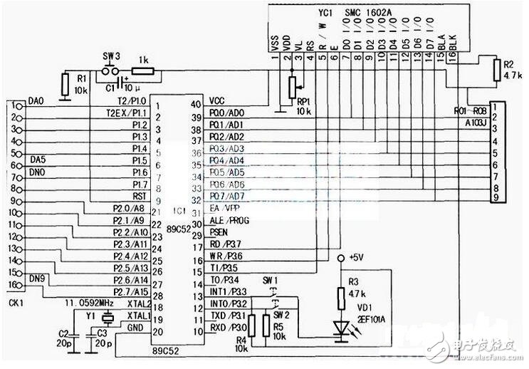
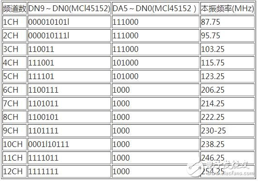
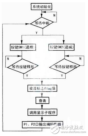
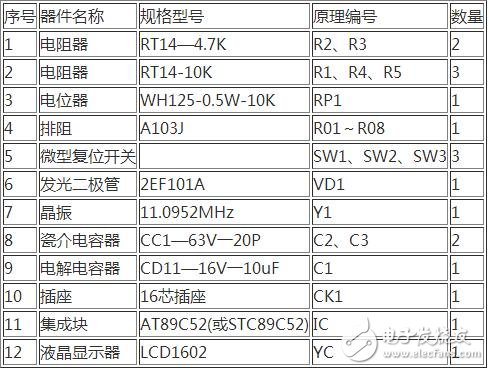
The main parameters of the LCD include contrast, brightness, display color, signal response time, viewing angle, etc. The determination methods of these parameters are: The contrast is related to the material of the panel, that is, the control IC, the filter and the alignment film have good contrast quality, but for the average user, the contrast ratio is 350:1, and the contrast requirement for professional users should be high. some. At present, the contrast ratio of high-end LCD has reached 500:1, 600:1, which can fully meet the needs of professional fields. The contrast is difficult to accurately measure with the instrument, and the sensory judgment can only be made by visual observation under the power-on state. Since the liquid crystal itself cannot emit light, it needs to be illuminated by an external light source, that is, a lamp tube, and the brightness is of course brighter, so the number of the lamps is directly related to the brightness of the LCD. The early LCD had only two tubes, and later developed into four tubes, and some high-end products had six tubes. In order to increase the brightness, the four lamps are designed in three forms: One is to put one tube on each of the four sides, but there is a phenomenon of black shadow in the middle; the second is to arrange the four tubes from top to bottom, although this method eliminates the middle shadow, but The effect is still not very satisfactory; the third is to place the tube in a "U" shape, using only 3 tubes, turning all the tubes into "U" shape, placed in parallel, thus achieving 6 The effect of the illumination of a tube. Using 3 tubes to bend them into a "U" shape, not only avoids the black shadow caused by the use of 4 tubes, but also avoids the use of 6 tubes to dissipate a large amount of heat and endanger the life of the display. The brightness is measured in units of cd/m2. If the brightness is too low, the picture will be dark. At present, the brightness of the TFT type LCD is about 200 cd/m2. For most users, the brightness of 150-200 cd/m2 is sufficient. Signal response time is the speed at which the LCD reacts to the input signal, usually in milliseconds (ms). According to the observation ability of the human eye, when observing the moving picture, the response time is more than 40ms ["1OOO?" 40: 25 (frame / s)], there will be hysteresis of the moving image, causing the image to appear afterimage or trailing. The smaller the response time, the better, but the liquid crystal needs a process from dark to bright, so the signal response time of the LCD should generally be between 1 and 20 ms, and not more than 30 ms. The viewing angle is divided into two aspects: horizontal angle and vertical angle: the horizontal angle is centered on the vertical central axis of the liquid crystal screen, and moves to the left and right to clearly see the angular range of the image; the vertical angle is parallel to the liquid crystal screen. The center axis is centered and moves up and down to clearly see the angular extent of the image. The viewing angle is in "?" and requires a viewing angle of 150? /120? (Horizontal and vertical). The minimum viewing angle is 120? /160? (horizontal/vertical), below this value is not acceptable. Display color refers to the representation of the displayed image in terms of color. Early LCDs only showed high color (256 colors) in color. Therefore, many manufacturers use the so-called FRC (FrameRateControl) technology to improve the color of the picture, but all that is obtained is "pseudo-color". With the continuous advancement of display technology, the current LCD color performance can reach full color (32-bit) mode. The screen refresh rate, which is the frequency at which the display refreshes during the display. It is related to the refresh rate of the picture. Different types of displays have different requirements on the refresh rate. For CRT monitors, the refresh rate is required to be above 75 Hz. Below this value, the observer will feel the picture flickering. The faster the refresh rate, the better the visual sense of the picture. For the LCD, the refresh rate is required to be 60Hz. Because in the LCD, each pixel continues to emit light until the non-illuminated signal is sent to the controller, so the LCD does not have flicker caused by constant charge and discharge. Therefore, when the refresh rate is 60 Hz, the LCD can obtain a good picture. At present, the LCD screen refresh rate standard is set in the range of 60-75 Hz, the purpose is to replace the CRT display in order to use flexibility and compatibility. The resolution is usually distinguished by high resolution and low resolution. The resolution has a direct impact on the quality of the image presented by the screen, but different types of displays have different resolution requirements. The image of a conventional CRT display is mainly realized by dots and lines composed of pixels, so the number of pixels is an important factor affecting the resolution. However, the resolution supported by CRT monitors is more flexible, and can be displayed regardless of high resolution or low resolution. LCD only supports "real resolution", which is high resolution, because LCD monitors can only display the best image performance under "real resolution". The true resolution of the LCD is defined as "fixed-point form", which can be set to the highest when used. Resolution is one of the most important technical indicators of the display. The higher the resolution, the better the display will be. However, the resolution of the LCD is different from that of the CRT display. It is arranged by pixels in rows and columns. How many pixels per line and how many pixels in each column are set and specified by the manufacturer, so the resolution of the LCD cannot be adjusted arbitrarily. Only when working in the nominal resolution mode, the LCD can achieve the best display. The control circuit of the MCU is as shown in the figure below. SW3 is the reset switch. When the reset switch SW3 is pressed, the circuit is reset, the MCU is in the initial working state (1CH); the reset switch SW1 or SW2 is pressed, the double phase-locked loop adjacent frequency modulator The output TV channels are respectively stepped up or down. All of these information transmissions are processed by the system software, and the digital coded information corresponding to the local oscillator frequency of the channel to be set is output to the CK1 socket by the P1 and P2 ports. The CK1 socket and the MCl45152AP described in the previous issue (Seventh issue of 2009) The corresponding ports are connected, forcing the dual phase-locked loop adjacent frequency modulator to switch the TV channel according to people's wishes, and displaying the currently set channel number and the local oscillator frequency on the LCD liquid crystal display. The table of correspondence between digital coded information and the number of preset channels and local oscillator frequencies displayed on the LCD screen is shown in the table below. 1. Program flow chart The program flow chart of the dual phase-locked loop adjacent frequency modulator system is shown in the figure below. When the system is normal, the initial state LCD displays CH1—87.25MFlz; when the reset switch SW1 or SW2 is pressed, the channel and frequency are correspondingly increased or decreased. If the LCD screen does not display properly when the system is running, check whether the LCD display subroutine is incorrect. If the code output is incorrect, check whether the table check program is wrong. If there is no change when the reset button is pressed, the problem may occur. Interrupt the subroutine to check if the interrupt is initialized or the subroutine is executed incorrectly. This circuit is a digital circuit. It is combined with high-frequency electronic circuits. In the case of a correct schematic diagram, the key to making a product is the success or failure. The key is how to typeset, because the high-frequency circuit contains very rich harmonics. Ingredients, these harmonic components interfere with the normal digital signal as the circuit board is routed and the power source drifts everywhere. Therefore, the signal should be removed from the bud by destroying it. Therefore, the following principles must be followed when formatting: (1) The layout of the components should be reasonable, the small signal components are in the front, and so on, and the final stage is at the end; in the case of satisfying the above layout, it is necessary to consider the appearance and neatness as much as possible, so that the products have a sense of grade. . (2) The negative (ground) power supply of each part of the printed circuit board, the printed board is grounded by a large area of ​​copper to further eliminate the interference sources of random fluctuations. The hardware circuit components of this control system are listed in the table below. 4.14 Mm Wrie To Board Connectors 4.14 mm Wrie To Board Connectors 4.14 mm Wrie To Board Connectors ShenZhen Antenk Electronics Co,Ltd , https://www.pcbsocket.com

Which main parameters of the LCD determine the quality of the LCD?
December 14, 2022