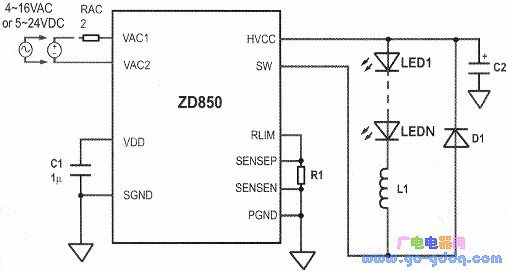
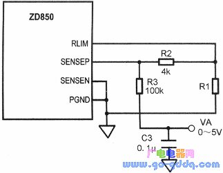
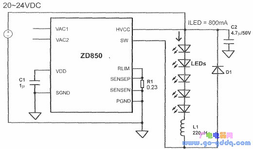
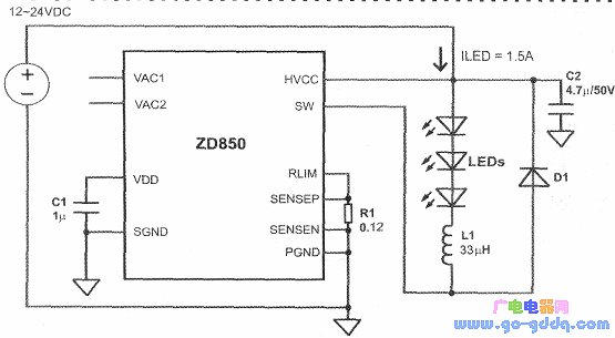
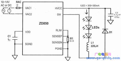
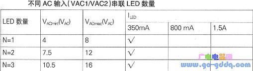
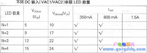
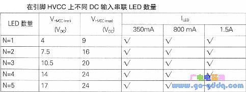
Zywyn's ZD850 monolithic IC is a constant off-time, high-power LED driver with a buck converter topology that delivers up to 1.5A of output current. The ZD850 operates from an AC voltage of 4 to 16 VAC or a DC voltage of 5 to 24 VDC to produce a regulated, programmable constant output current for high power LEDs. The ZD850 chip integrates an AC/DC bridge rectifier, a linear regulator, a high voltage NDMOS power switch, and thermal and overvoltage protection circuits. Based on the high efficiency pulse frequency modulation control design, the ZD850's minimum turn-off time is set at 1.5μs. Excellent LED current regulation over the entire supply voltage range with conventional or E-type transformers. The main applications of the ZD850 are LED lighting power supplies for industrial lighting, decorative lighting, traffic and automotive lighting. Pin function and main parameters The ZD850 is available in a 16-lead bare TSSOP package with pinouts as shown below. The above table lists the various pin functions of the ZD850. The electrical characteristics of the ZD850 are shown in the table below. Basic functions and component selection The ZD850 typical application circuit is shown above. 4 - 16VAc AC voltage or 5 - 24Voc DC voltage input from the ZD850 pins VAC1 and VAC2. When the two input pins VAC1, VAC2 are left floating, the DC voltage can also be input from the HVCC terminal of the IC. At power up, a small resistor RAC connected to input VAC1 (or VAC2) is used to limit the inrush current generated when charging capacitor C1. It is recommended that RAC use 2Q non-flammable metal film resistor (power consumption is 0.25W). 1. The output current sets the current sensing resistor R1 connected between the ZD850 pins SENSEP and SENSEN to set the LED current. The peak-to-peak ripple current IRIPPLE in inductor L1 is typically about 15% of ILED. When the ambient temperature is 25 °C, the R1 value is: R1=0.2V/(}LED+△IRIPPLE/2)-0.2\//ILED+O.151LED/2=0.2V/1.075lLEDO If the case temperature exceeds 400C, Rl The value can be calculated from Rl = 0.12 V / (ILED + Δ1 RPPLE / 2) ≈ 0.12 V / 1.075 ILED. 2. The inductor selects Ll as the inductor in the buck converter. To prevent the output current from changing with voltage, choose a larger inductor value. The L1 inductance can be obtained by using L1 = NVF × toff / ΔIRIPPLE ≈ NVF × 1.5 μs / 1.151 LED. For example, if there are 3 LEDs connected in series, ILED=350mA, the forward voltage drop of each LED is VF=3.3V, DC voltage is input from the HVCC end of the IC, and the inductance value is L1=3×3.3V×1.5× 10-6S/0.35A×0.15=282uH, and L1=220μH was selected. 3. The diode selection diode D1 provides a path for the inductor L1 to release energy (ie, discharge) when the ZD850 internal NDMOS transistor is turned off, so that current will still pass through the LED string. Since the maximum voltage on the lC pin HVCC is 24VDC, the reverse breakdown voltage of D1 should be higher than 40V, and its forward current cannot be lower than 2ILED. 4. Capacitor Selection The decoupling capacitor C1 on the ZD850 pin VDD is 1μF/16VDCO. The decoupling capacitor C2 on the IC pin HVCC selects 4.7μF for DC applications and 470μF for AC operation. 5. The LED dimming LED dimming circuit is shown in the figure. A PWM signal of 500 Hz to 50 kHz is applied to the VA terminal to implement PWM dimming. The dimming ratio is inversely proportional to the PWM duty factor (range 10% to 90%). Analog voltage dimming can be achieved by applying a 0-5V DC voltage to the VA terminal. As the voltage increases from OV to 5V, the LED current will decrease and the brightness will decrease. The number of application circuits and series LEDs is determined. The application circuit example ZD850 drives the circuit of five series LEDs as shown in the figure above. The forward voltage drop of each LED is VF=3V, and the working current is ILED=800mA. The DC voltage of 20~24VDC is input from the IC pin HVCC, and the pins VAC1 and VAC2 are suspended. The figure above shows the circuit in which the ZD850 drives three LEDs. The current through the LED is 1.5A, the VF of the single LED is 3V, and the DC voltage of 12-24Voc is applied from the IC pin HVCC. The ZD850 drives three 3V, 300~500mA series LEDs as shown in the figure above. 10 - 14V AC voltage or DC voltage is input from IC pins VAC1 and VAC2. When the DC voltage is input, C2 selects a 4.7μF/16VDC capacitor. When the AC voltage is input, C2 selects a 470μF/16VDC capacitor. The LED can be selected from the US Lampe's ×Lamp7090×RE series. When the AC voltage is input, the circuit can be connected to an E-type transformer as shown in the figure below. 2. Determination of the number of LEDs in series The number of LEDs (N) in the LED string driven by the ZD850 is related to the input voltage range, whether it is AC or DC input, and whether it is at the VACINAC2 input or at the pin HVCC input (DC voltage input only). The minimum input voltage VHVCC(min) on the IC pin HVCC should be greater than the total voltage of the LED string plus 1V (ie NvF+1V). The maximum input voltage VHVCC(max) should be no more than 2 times the total voltage of the LED string (ie 2N). -VF). Let the forward voltage drop of each LED be VF=3V, and the number of LEDs connected in series with different input voltages is shown in the following table. Indoor Patch Cord,Armored Patch Cord,Simplex Armoured Patch Cord,Duplex Armoured Patch Cord,Outdoor Duplex Armoured Patch Cable ShenZhen JunJin Technology Co.,Ltd , https://www.jjtcl.com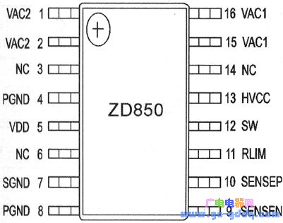
Pin number name Features VAC2 1, 215, 16 4——16VAc or 5——24VDC voltage input VAC1 13 HVCC The rectified DC voltage is output. When the pins VAC1 and VAC2 are left floating, this pin can be used as a DC voltage input of 5 - 24 VOC voltage. 5 VDD 3.2V internal regulator output, this pin is connected to a 1uF/16VDC decoupling capacitor between external and SGND 11 RLIM Connect a resistor from this pin to ground to set the LED driver output current 7 SGND Signal ground, all small signal components are connected to this end 4,8 PGND Power level ground, high voltage decoupling capacitor is connected to the end 12 Sw Power switch node 10 SENSEP RLIM sensing is being connected 9 SENSEN RLIM senses negative connection 3, 6, 14 NC Do not connect, it must be suspended 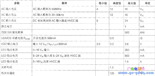
January 01, 2023