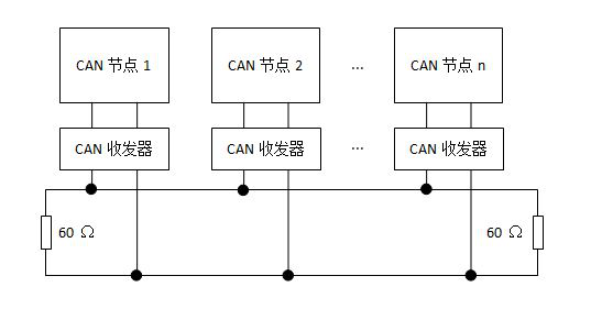
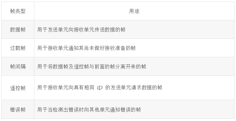
In the first two days of push, we introduced the I2C and SPI buses, but they are mostly used in "lightweight" applications where the transmission distance is short, the protocol is simple, the data volume is small, and the communication is mainly for IC (Integrated Circuit). The CAN bus is different. The CAN bus defines a better physical layer and data link layer, and has a wide variety of upper-layer protocols. What is the CAN bus? CAN is the abbreviation of "Controller Area Network", which is "Controller Area Network", which is an ISO standard serial communication protocol. The CAN bus was developed and designed by the German company BOSCH to meet the needs of the increasingly large electronic control system in the car. Its biggest feature is its high expandability, high-speed communication that can withstand large amounts of data, and high stability. The ISO organization standardized the CAN bus through ISO11898 and ISO11519, which established the status of the European automotive bus standard early. Today, the CAN bus has been highly recognized by the industry, and its applications have also extended from automotive electronics to industrial automation, marine, medical equipment, industrial equipment and other fields. CAN bus network topology The physical connection of the CAN bus requires only two wires, often referred to as CAN_H and CAN_L, for data transmission via differential signals. The CAN bus has two levels, recessive and dominant, which have an AND relationship between the drain I/O level signals: · If the recessive levels meet, the bus behaves as a recessive level; · If the dominant levels meet, the bus behaves as a dominant level; • If the recessive level and the dominant level meet, the bus behaves as a dominant level. A typical CAN bus network topology is shown in Figure 1. Note that the termination resistors at both ends are required. Figure 1. CAN bus network topology Several data frames of the CAN bus The CAN bus protocol specifies five types of frames, namely data frames, remote frames, error frames, overload frames, and frame intervals. In practice, data frames are most frequently used. The use of various frames is shown in Table 1. Table 1. Types and uses of CAN bus data frames CAN bus features The CAN bus network is a true multi-master network. When the bus is idle, any node unit can apply to become the host and send messages to the bus. The principle is that the node unit that first accesses the bus can obtain the control of the bus; when multiple node units try to acquire the control right of the bus at the same time, an arbitration event will occur, and the node unit with high priority will obtain the bus control right. In the CAN protocol, all messages are packaged and sent in a fixed data format. When two or more node units simultaneously transmit information, the node identifiers (often referred to as IDs, also packed in a fixed data format) determine their respective priority relationships, so the ID does not represent the destination address of the data transmission, but represents The priority of each node accessing the bus. In this way, the CAN bus does not have the concept of other bus "addresses". When adding a node unit on the bus, the hardware and software of other node units connected to the bus do not need to be changed. The communication speed of the CAN bus is related to the bus length. In the case where the bus length is less than 40m, the data transmission rate can reach 1Mbps, and even if the bus length rises to 1000m, the data transmission rate can reach 50Kbps, regardless of the rate or the transmission distance. Significantly better than the popular RS232, RS485 and I2C buses. For bus errors, the CAN bus has three countermeasures: error detection function, error notification function, and error recovery function. It should be expressed in the following three points: all unit nodes can automatically detect errors on the bus; detect the wrong node unit. The error will be notified to other node units immediately; if the unit that is sending the message detects an error on the current bus, it immediately forces the current transmission to be canceled and the message is sent repeatedly until it succeeds. Each node on the CAN bus can be judged by a temporary error (such as a momentary strong interference) or a continuous error (such as a bus break) on the current bus error. When a persistent error occurs on the bus, the node unit that caused the fault automatically leaves the bus. There is theoretically no limit on the number of nodes on the CAN bus, but it actually receives time delays on the bus and limits on electrical loads. By reducing the maximum communication rate, the number of connections of the node unit can be increased; conversely, by reducing the number of connections of the node unit, the maximum communication rate can be increased. Kitchen Range Hood Motor,Range Hood Motor,Kitchen Range Hood,Range Hood Fan Motor WUJIANG JINLONG ELECTRIC APPLIANCE CO., LTD , https://www.jinlongmotor.com

March 12, 2023